* Send a message between two projects. * Document your work to the group work page and reflect on your individual page what you learned.
Individual Assignment
* design, build and connect wired or wireless node(s) with network or bus addresses and a local input and/or output devices.
checklist
☑ Linked to the group assignment page. ☑ Documented your project and what you have learned from implementing networking and/or communication protocols. ☑ Explained the programming process(es) you used. ☑ Ensured and documented that your addressing for boards works. ☑ Outlined problems and how you fixed them. ☑ Included design files (or linked to where they are located if you are using a board you have designed and fabricated earlier) and original source code. ☑ Included a ‘hero shot’ of your network and/or communications setup.
Group Assignment Reflection
This week I need to spend a bit of my time to share what I have encountered with my partner - Florimond Chu on this week group assignment. We are told to send a message between both our projects. Both of us have dificuilties on handling the topic - our current development board doesn't allow us to direct apply on this week topic, instead we need to have additional devices to support the assignment. We are fortunate enough to have Mr. Steven Chew to give us a full-day tutorial session on explaining the theory, and also our Ex-Fablab student - Zi Hon to work with us on coming out a code to get through this week group assignment. Although there are still a lot of unknowns waiting ahead of us, but surely this will helps us to get closer to what we are aiming for for this week.
Measure something: add a sensor to a microcontroller board that you have designed and read it.
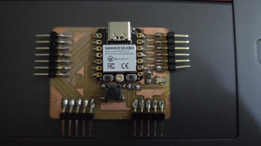
Before I go into this week individual assignment, i have a dilemma on whether wanna change our own development board to SEEED Xiao ESP32C3 micro-controller due to the capability of using Bluetooth or Wi-Fi connection, or remain as the current development board with SEEED Xiao RP2040 micro-controller to learn a bit more on networking. After discussed with both my FabAcademy partner - Florimond Chu and my instructor - Mr. Steven Chew, I have decided to make another development board using ESP32C3 micro-controller. With the knowledge that I have learnt from week 8, it wasn't a tough job to re-machining a new printed circuit board for my new development board. Also, as far as both SEEED Xiao RP2040 and SEEED XIAO ESP32C3 micro-controller board have the similar characteristic on their pin-outs, I can just refer back to my previous SEEED Xiao RP2040 board to solder all the components on my new PCB. Special thanks to my partner - Florimond Chu who helps me to complete my PCB by soldering the last 2 1x5 Pin Heads at the bottom of the PCB. Photo below shows the completion of my NEW SEEED Xiao ESP32C3 PCB.
Up next, I need to test if my new SEEED Xiao ESP32C3 PCB works. I just run a simple BLINK program (reference from Getting Started with Seeed Studio XIAO ESP32C3): Something STRANGE!! After I uploaded the program, the LED on my PCB doesn't function correctly as what I did on my SEEED Xiao RP2040 PCB - the LED never blink itself after the code has been uploaded. Instead, the LED will only starts to blink when I press the BOOT Button on the SEEED Xiao ESP32C3 micro-controller board, which is not what I noticed when I tried on SEEED Xiao RP2040 micro-contorller board.
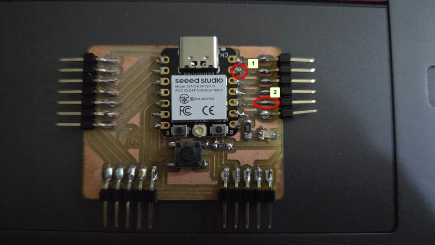
I tried on different code with the board but still get a positive result. Hence, I am seeking help from my instructor - Mr. Steven Chew on checking on both the code and the PCB. In the end, it was the discontinuity on the GND point and D9 pinout. I quickly go and perform "Emergency Surgery" on my SEEED Xiao ESP32C3 PCB and check the 2 points' continuity. After reparing, I quickly upload the same code and test, IT WORKS!!! (with video proved.)
Implementing a Web Server
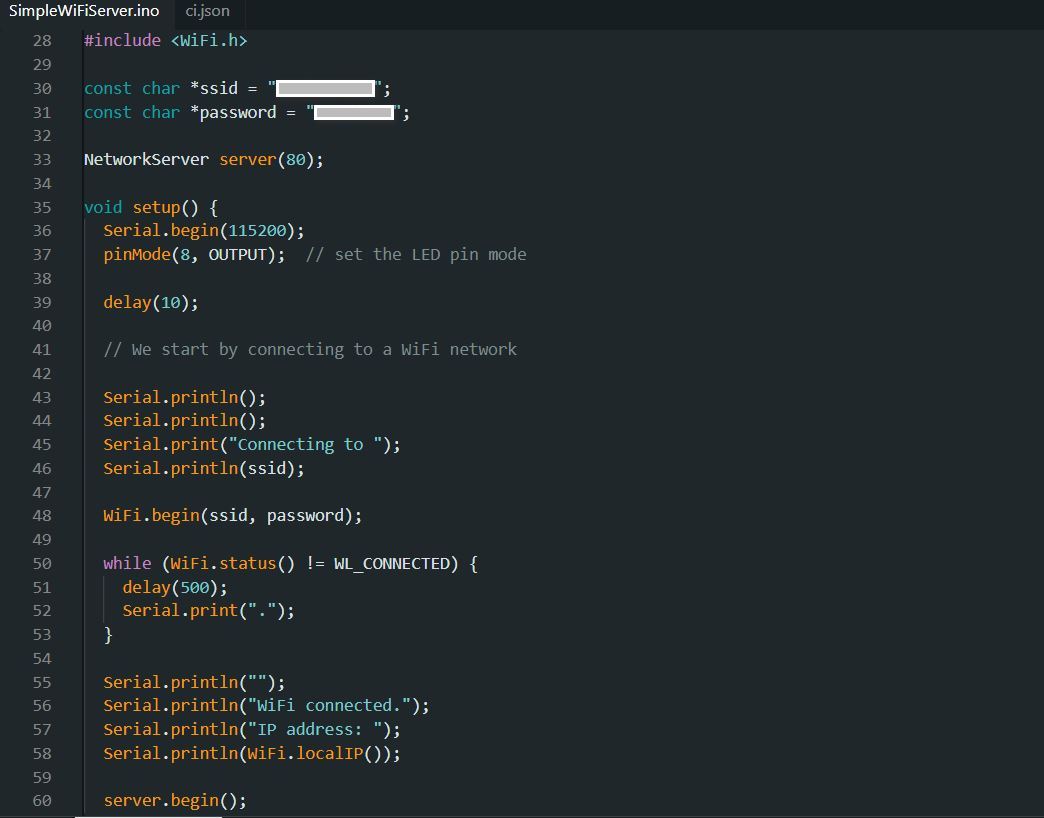
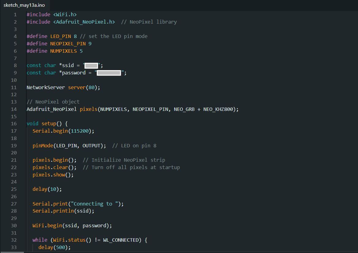
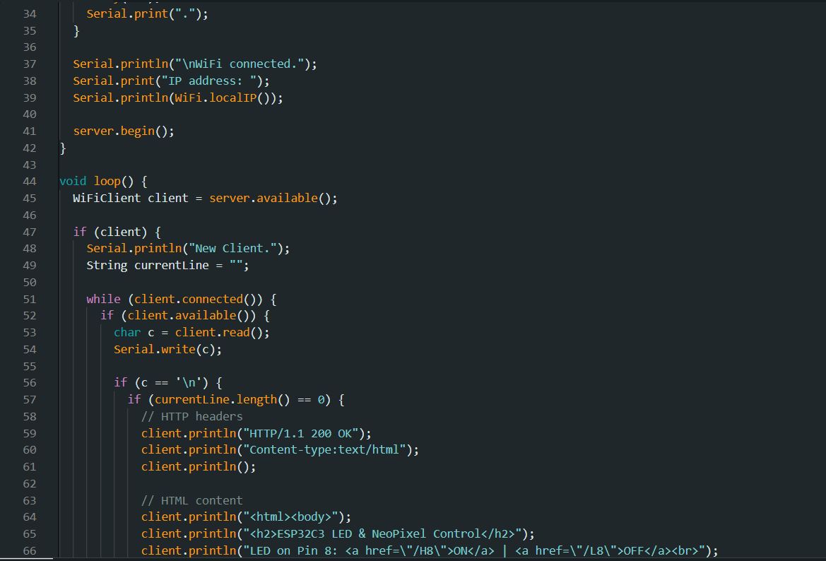
Frankly speaking, I don't how can I start for this week individual assignment. For the start, I am using Arduino IDE example --> WiFi --> SimpleWiFiServer. The code are shown below, where my single LED was set at Pin 8 on my development board, and I am connecting to my home wireless network: As a result, I can use the webpage where the IP address was mentioned on the serial monitor to toggle the LED to switch on and off, as shown in the video below:
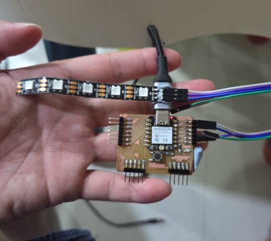
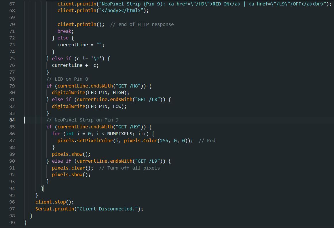
My instructor - Mr. Steven Chew proposed to me saying that try to expand the function to toggle not just a single LED, but on 2 separate LEDs (or other outputs) to complete the assignment. Based on the example, he explained to me what are the key points that need to take note on adding a second function onto the same code. Unfortunately, I do not have any available LED light on hand, so I switch to toggle a NeoPixel strip instead of a LED light. To control two different outputs connected to Pin 8 (LED onboard) and Pin 9 (Connected to NeoPixel strip) of an ESP32C3 using a web interface, you need to: 1. Declare both pins as outputs. 2. Modify the HTML to provide controls for both LEDs. 3. Add handling logic for additional URL paths (e.g. /H8, /L8, /H9, /L9) to control each output independently. I have tried to refer back to my previous assignment on week 10 to capture the basic code line that are required to run a NeoPixel strip. The key changes compared to the example are: 1. Include the NeoPixel library. Initialize the NeoPixel strip on Pin 9. Include the commands to turn NeoPixels on/off with red color (if want to try on other colours, ex Green colour, simply just change the colour code from (255, 0, 0) to (0, 255, 0)). Here is the updated code: IT WORKS!!!
Reflection
As mentioned earlier, I have ZERO knowledge to start and complete this week assignment, Although it was an exciting week to explore new skills, I don't have much time to experiment, as I still have my major task - the final project on making my own musical box. Moreover, I find that the connectivity was not that stable, as it required to restart a few times then I can toggle the functions on the website. So, as a conclusion, I won't be adding this function to my final project.